Introduction
The purpose of a laboratory exhaust system is to capture potentially harmful or odorous pollutants from the laboratory environment and safely expel them from the building such that they don’t re-enter the building, its neighbors, or impact other nearby sensitive locations (receptors) at concentrations exceeding health limits or odor thresholds.
Guidance is provided in various standards and best practice guides,,,, which typically define the minimum stack heights (3 m to 1.25 times the height of the building) and exit velocities (10 m/s to 15 m/s). However, these minimal requirements describing the physical characteristics of the fan and stack system do not address the primary concern: the contaminants potentially present in the exhaust stream and the proportion of the exhaust plume present at the areas of concern.
One guide that provides both general information for exhaust and intake designs, and offers various quantitative approaches that can be used to determine expected concentration levels at locations of interest, is “Modeling Exhaust Dispersion for Specifying Acceptable Exhaust/Intake Designs”. This guide describes a method to establish an appropriate exhaust design criterion to specify the concentration level at which exposure to the exhaust will still result in acceptable air quality. It also describes a variety of methods by which the exhaust concentration can be predicted.
This article describes the use of physical modeling in an Atmospheric Boundary Layer (ABL) wind tunnelto predict exhaust concentration as a function of wind direction and wind speed, providing the necessary information to allow the laboratory exhaust system to be controlled as a Variable Air Volume (VAV) system that will meet the established design criterion while consuming the minimum amount of exhaust fan electrical energy.
Background
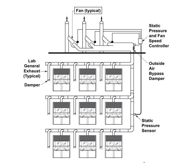
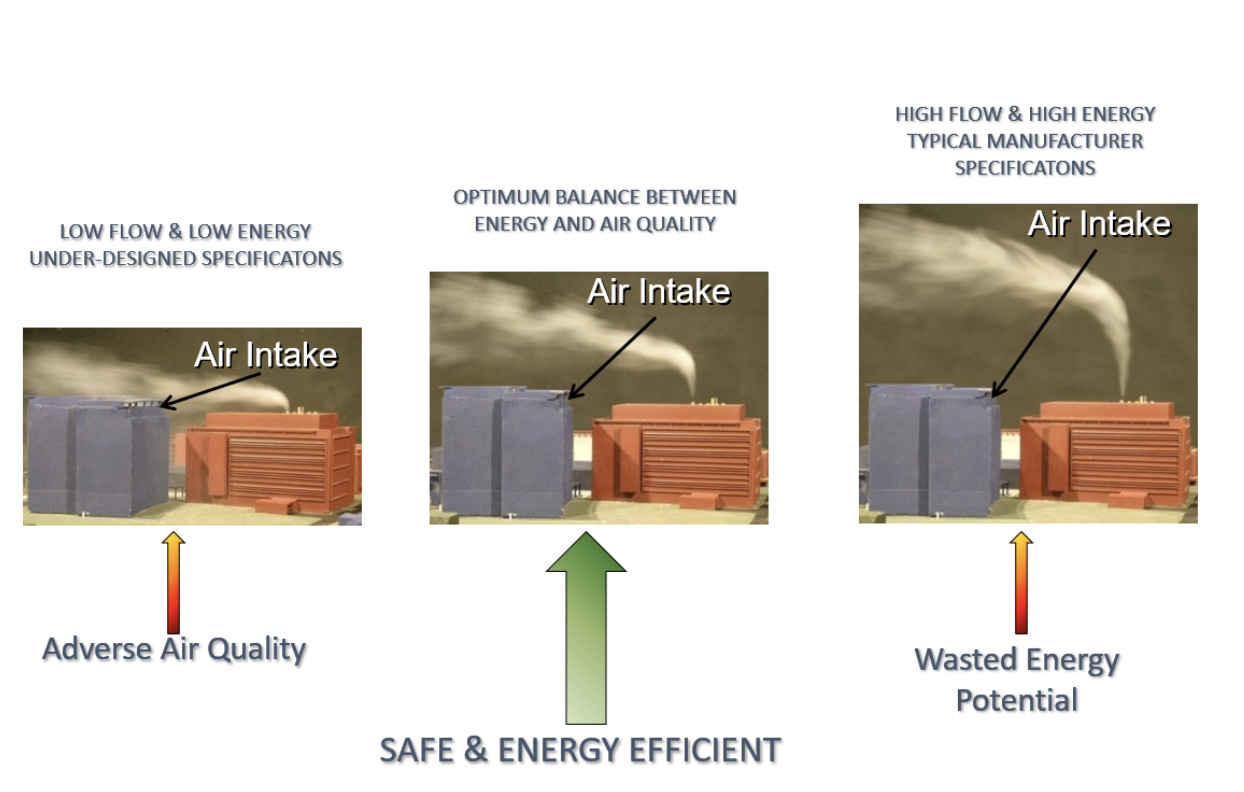
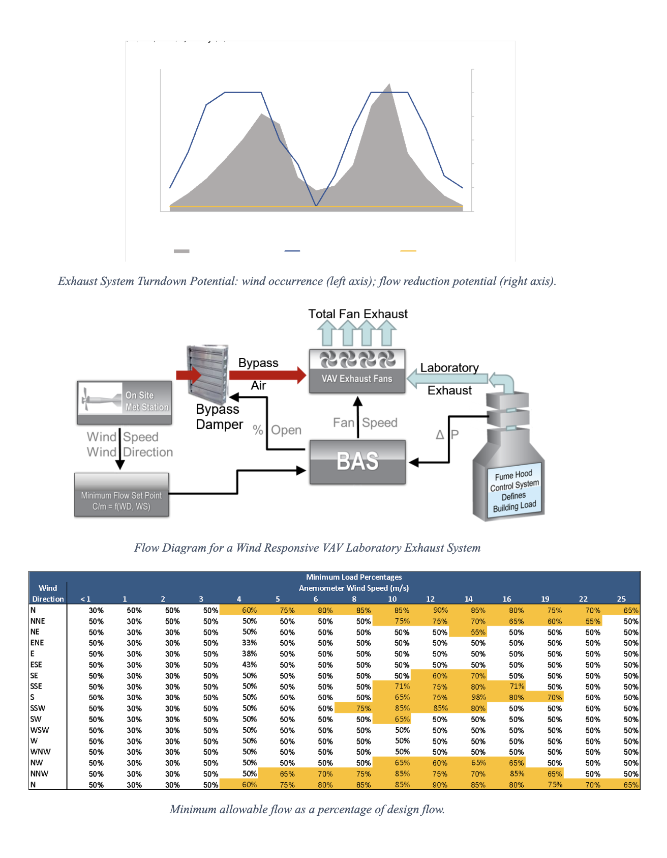
Laboratory buildings can consume between 10 and 100 times as much energy per unit area as a typical office building,with the supply air and conditioning systems accounting for approximately 60% of the ventilation system energy used. The laboratory exhaust systems consume about 40% of the ventilation system energy, equivalent to 30% of the total building energy consumption., Designers often focus on energy savings strategies associated with the supply air, but typically have overlooked energy savings potential within the exhaust system. Manifolded exhaust systems are commonly designed such that the exhaust fans operate at constant volume (CV) and respond to variations in the building exhaust requirements by opening a bypass damper at the exhaust plenum to make up the difference between building demand and the CV requirements of the exhaust system, Figure 1. The CV parameters of the exhaust system are typically set based on general guidance, as discussed above, that may – or may not – be tied to specific exposure criteria. This may result in systems such as shown at the left and right of Figure 2. On the left of Figure 2, the CV system is under-designed and the neighboring building air intake is exposed to concentrations in excess of the design criterion. On the right of Figure 2, the plume rises dramatically above all the buildings, meeting the design criterion by a significant margin. However, this dramatic plume rise comes with a high energy cost as the height of the plume rise is a function of the power consumed by the exhaust fan. In the center of Figure 2, the exhaust system is optimized in that only the momentum required to achieve the exposure criterion is used.
Dispersion Modeling to Optimize Laboratory Exhaust Energy Consumption
Designing a laboratory exhaust system to utilize a Variable Air Volume (VAV) exhaust system allows the exhaust ventilation system to matchthe supply ventilation airflow of the building under most circumstances. This allows the designer to take full advantage of energy-saving opportunities associated with minimizing airflow requirements for the laboratory. However, just as arbitrarily reducing the supply airflow may adversely affect air quality within the laboratory environment, blindly converting an exhaust system to VAV without a clear understanding of how the system will perform can compromise air quality inside and at nearby sensitive locations. Therefore, before employing a VAV system, the potential range of operating conditions should be carefully evaluated through a detailed dispersion modeling study.
Wind Tunnel Dispersion Modeling
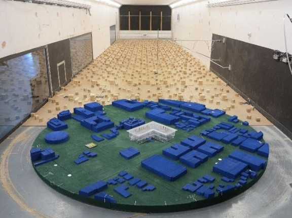
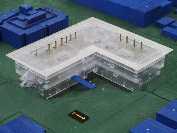
Wind-tunnel modeling is often the preferred method for predicting maximum concentrations for stack designs and locations of interest, and is recommended because it gives the most accurate estimates of concentration levels in complex building environments.4Mathematical methods can be used, but these are less accurate and require conservative choices to be made and, more often than not, will result in higher minimum momentum requirements with reduced energy savings potential. Typically, a scale model of the building under evaluation, along with the surrounding buildings and terrain within a 300 meter radius, is placed in an atmospheric boundary layer wind tunnel,Figure 8. A tracer gas is released from the exhaust sources of interest, and concentration levels of this gas are measured at receptor locations. The model can be rotated in the wind tunnel, providing data for all 360 degrees of wind conditions, as well as at multiple wind speeds for each wind direction, providing concentration predictions as a function of wind speed and wind direction. These concentration values are compared against the appropriate design criteria to evaluate the acceptability of the exhaust design. ASHRAE4and the EPA provide detailedinformation on proper scale-model simulation and testing methods.
Wind-tunnel studies are highly technical, so care should be taken when selecting a dispersion modeling consultant. Factors such as past experience, proper calibration of the wind tunnels10, and technical qualifications of the staff are extremely important.
Variable Air Volume Laboratory Exhaust Control
The two most common strategies that can be used for operating VAV laboratory exhaust systems are described as: Simple TurndownVAV control (ST-VAV); and Wind-responsive VAV control (WR-VAV). These methods may also be described as Passive VAV and Active VAV.
Hypothetical Project
The following is an example illustrating a hypothetical Wind-responsive VAV control system for a laboratory building in Hyderabad. The example project is assumed to be located at the India Institute of Chemical Technology, approximately 22 km from Rajiv Gandi International Airport, Figure 4.
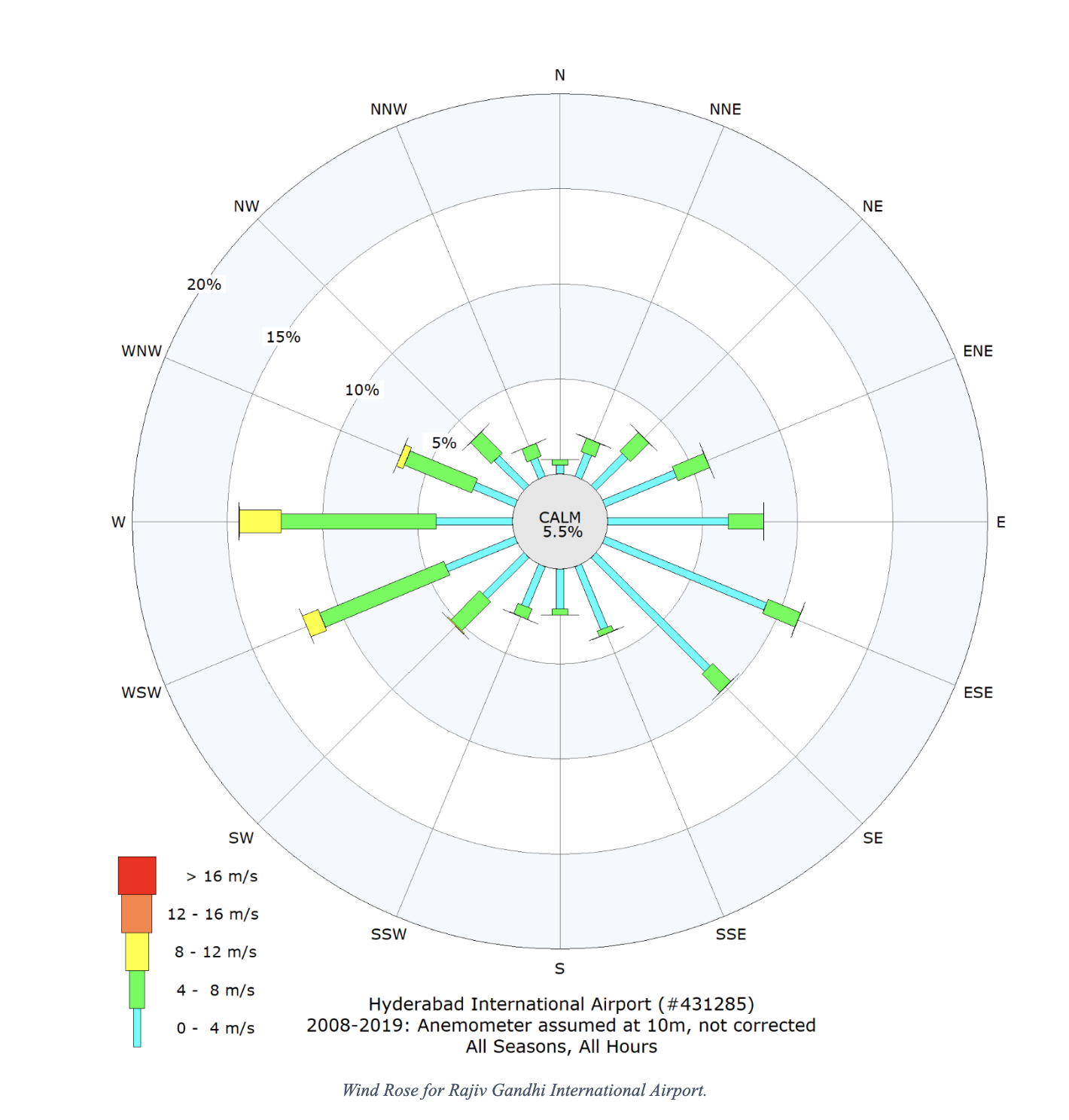
A wind-rose for the airport is shown in Figure 5. Just from the wind rose, considerable potential for energy savings is expected due to the limited occurrence of northerly and southerly winds, and the majority of higher speed winds occurring from the west. Properly locating the air intakes to take advantage of these winds will enable the exhaust system to operate at the minimum conditions most of the time, allowing the WR-VAV control system to provide significant energy savings compared to a Constant Volume (CV) system.
The hypothetical building is equipped with a15 m3/smanifolded exhaust system comprised of 4 exhaust fans. The results of an ABL wind tunnel dispersion modelindicate that a ST-VAV system would only achieve a flow (i.e., momentum) reduction of about 2% of the design flow, due to the possibility of a high concentration a nearby air intake, Figure 6. Therefore, a WR-VAV system is recommended. In this case, the exhaust system can be turned down to 50% of design flow for many wind conditions, with the limit of 2% of design flow only under the critical conditions, the relatively rare south winds. To implement such a system, a local anemometer must be installed on or near the building, with the signal collected by the Building Automation System (BAS), Figure 7.The WR-VAV system is implemented in the BAS via a turndown table such as shown in Figure 8.
For this project, the estimated savings for the WR-VAV versus a traditional CV system are illustrated in Figure 9, with a potential energy savings of 102 lakh rupees annually.
Summary and Conclusions
An accurate assessment of exhaust dispersion can be used to provide exhaust/intake designs that are optimized for safety and energy consumption. Exhaust fan systems should be designed considering the pollutants emitted, allowable exposures to those pollutants, and the energy consumption required to achieve a safe, yet energy efficient design. Blindly applying VAV to the laboratory exhaust system using “rule of thumb” operating parameters can be detrimental to the air quality at air intakes and other locations of concern.
A hypothetical project is presented where both Simple Turndown VAV and Wind-responsive VAV control systems are evaluated through use of a dispersion modeling assessmentconducted using an Atmospheric Boundary Layer wind tunnel modeling program where potential energy savings of 102 lakh rupee annual is possible.
Courtsey – John J. Carter, Vice President, Ryan Parker